There is a second way to use the CAN bus: in “single wire” mode (SW-CAN). But before I go into that, let me set up a dual-node bus, using standard MCP2551 transceivers for a “normal” CAN bus with CAN-HI and CAN-LO signals. Here is my little breadboard setup:
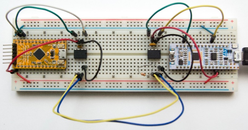
On the left: a HyTiny from Haoyu Electronics. It’s a nice alternative to the Blue Pill with a convenient 6-pin programming header on the end (power, SWD, and serial). For all intents and purposes, it’s the same as a Blue Pill - just smaller (and with fewer I/O pins).
On the right: a Nucleo-L432 board from STM. This is a different STM32 family (lower power, but also higher performance and Cortex M4 iso M3). Just to pick a different µC.
One reason for choosing different µCs, is that it lets me test and develop more CAN h/w drivers in JeeH, alongside the STM32F4xx. And it shows that CAN is not µC-specific.
Multi-PlatformIO
This also lets me show how a PlatformIO project can be used for multiple
configurations. So here we go again, with a new project folder and two files
in it. First platformio.ini:
[env:f103]
build_flags = -D STM32F1
platform = ststm32
board = bluepill_f103c8
framework = stm32cube
upload_protocol = blackmagic
upload_port = /dev/cu.usbmodemBDC8CDF1
monitor_speed = 115200
lib_deps = jeeh

[env:l432]
build_flags = -D STM32L4
platform = ststm32
board = nucleo_l432kc
framework = stm32cube
upload_protocol = stlink
monitor_speed = 115200
lib_deps = jeeh
Unlike my previous example projects, this configuration defines two build
“environments”. The other file is of course src/main.cpp, which contains
the following demo code:
#include <jee.h>

#if STM32F1
PinA<1> led;
UartBufDev< PinA<9>, PinA<10> > console;
#elif STM32L4
PinB<3> led;
UartBufDev< PinA<2>, PinA<3> > console;
#endif

int printf(const char* fmt, ...) {
    va_list ap; va_start(ap, fmt); veprintf(console.putc, fmt, ap); va_end(ap);
    return 0;
}

CanDev can;

int main() {
    console.init();
    console.baud(115200, fullSpeedClock());
    led.mode(Pinmode::out);

    can.init();
    can.filterInit(0);

    uint32_t last = 0;
    while (true) {
        if (ticks / 500 != last) {
            last = ticks / 500;
#if STM32F1
            bool ok = can.transmit(0x654, "87654321", 8);
#elif STM32L4
            bool ok = can.transmit(0x321, "ABCDEFGH", 8);
#endif
            printf("T %d ok %d\n", ticks, ok);
        }

        int len, id, dat[2];
        len = can.receive(&id, dat);
        if (len >= 0) {
            printf("R %d @%x #%d: %08x %08x\n", ticks, id, len, dat[0], dat[1]);
            led.toggle();
        }
    }
}
The basic logic is to send a CAN bus packet every 500 ms and to report each
incoming packet. The code is slightly more involved because it adapts to two
different µC boards. See the #ifdef STM32F1 and #elif STM32L4 conditionals.
Trying it out
- For building and uploading to the HyTiny, use:
pio run -t upload -e f103 - For building and uploading to the Nucleo, use:
pio run -t upload -e l432
Each board reports its activity on a different serial port. Here is the Nucleo output:
R 0 @654 #8: 35363738 31323334
R 412 @654 #8: 35363738 31323334
T 500 ok 1
R 913 @654 #8: 35363738 31323334
T 1000 ok 1
R 1414 @654 #8: 35363738 31323334
T 1500 ok 1
R 1915 @654 #8: 35363738 31323334
T 2000 ok 1
R 2416 @654 #8: 35363738 31323334
T 2500 ok 1
R 2917 @654 #8: 35363738 31323334
[...etc...]
Both on-board LEDs will blink, toggled by messages sent from the other board.
Single Wire CAN
But as I mentioned earlier, there is another way to use the CAN bus. We can do away with the CAN bus driver chips and perform all data communication over a single signal wire. Note that this still needs a common ground level, as every electrical signal does.
The trick is possible because a CAN bus acts as one long “passive AND gate”. That’s what makes CAN tick, with all its address resolution, prioritisation, and its real-time guarantees. All we need, is that wired-OR property of the bus.
The idea is to add a pull-up and to put all the transmit pins in “open drain” mode. For µCs where that’s not possible, a diode can be added so each transmitter can only pull down.
Here’s the new – and fairly dramatically – simplified setup:
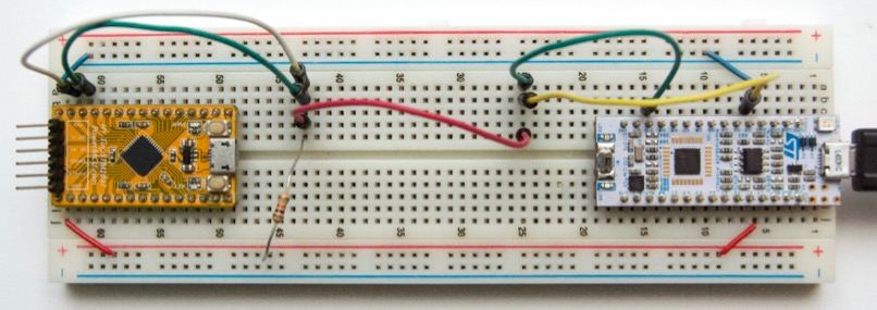
All the extra circuitry is gone. Just three connections left: the SW-CAN signal, and power (5V and GND, through two power rails). Also, there’s now a 1 kΩ pull-up to 5V (or 3.3V).
The one crucial change in the application code, is that we need to configure the transmit pins as open-drain outputs. Which is trivial, since JeeH provides an init option. Change:
can.init();
… to this:
can.init(true);
Sooo… does this work? Sure, the LEDs still blink as before. It’s still a bi-directional shared CAN bus, even though it’s now a single signal wire. Will it run as fast? Yes, 1 Mbps works fine (but probably only over short distances). Is it as robust? No, the voltage levels must stay within the permitted limits of the GPIO pins (which are 5V-tolerant, but that’s about it). There’s no driver chip to optimally condition the signal or protect the µC from any spikes.
And there you have it: with three wires, an “interconnect” can be created which distributes 5V power and communicates in a pub-sub fashion over a shared real-time bus.
References
- The code for this demo can be found here.