Demo time! As test setup, I’m going to use an F4-based STM32 µC, since it has two CAN bus controllers. It’s easier to write a quick test for a single system. And since I have these boards lying around, that’s what I’ll use: a 32F429-DISCO with an Open429Z-D:
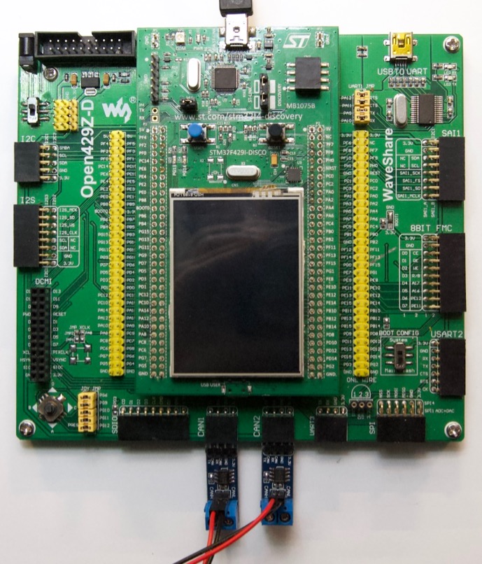
The breakout board adds a USB-to-serial interface and headers to plug in two CAN bus drivers (for level translation, as described in part 1). They each have a 120 Ω termination resistor, so all that’s needed for a minimal CAN bus is the 2-wire jumper between them.
The F429-DISCO board includes an ST-Link (v2.0) for uploading code. No need to grab a Black Magic Probe or other programming tool.
There’s a lot more functionality on these two boards, none of which will be used here.
The demo code
As with all PlatformiIO projects, initial setup is a matter of creating a new
empty project folder, with two files: platformio.ini and src/main.cpp.
Here is the platformio.ini file, it should look familiar by now:
[env:f429]
build_flags = -DSTM32F4
platform = ststm32
board = disco_f429zi
framework = stm32cube
upload_protocol = stlink
monitor_speed = 115200
lib_deps = JeeH
And here is the initial demo application I came up with for src/main.cpp:
#include <jee.h>

UartBufDev< PinA<9>, PinA<10> > console;
#include <../../common.h>

CanDev<0> can1;
CanDev<1> can2;

int main() {
    console.init();
    constexpr uint32_t hz = 180000000;
    enableClkAt180MHz();        // the F429 mac clock rate is 180 MHz
    console.baud(115200, hz/2); // APB2 is /2 to stay within 90 MHz max
    enableSysTick(hz/1000);     // recalibrate SysTick to fire every 1 ms

    printf("hello!\n");

    can1.init();
    can2.init();

    can1.filterInit(14); // always set filters via can1

    uint32_t last = 0;
    while (1) {
        if (ticks / 500 != last) {
            last = ticks / 500;
            printf("T %d\n", ticks);
            can1.transmit(0x123, "abcd1234", 8);
        }

        int len, id, dat[2];
        len = can2.receive(&id, dat);
        if (len >= 0) {
            printf("R %d @%x #%d: %08x %08x\n", ticks, id, len, dat[0], dat[1]);
        }
    }
}
Every 500 ms, an 8-byte packet is sent out on can1 with a fixed payload
("abcd1234"). And whenever a packet comes on can2, its details are printed
on the console.
Let’s see it run
When all the configuration details are right, compiling and uploading is a
matter of typing pio run -t upload. The serial USB port will then show the
printf output:
hello!
T 500
R 500 @123 #8: 64636261 34333231
T 1000
R 1000 @123 #8: 64636261 34333231
T 1500
R 1500 @123 #8: 64636261 34333231
T 2000
R 2000 @123 #8: 64636261 34333231
T 2500
R 2500 @123 #8: 64636261 34333231
[...etc...]
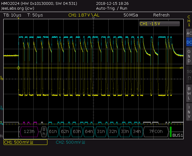
With a scope that has CAN protocol decoding built-in, we can see what the bus looks like:
Some notes and observations:
- CAN-HI is the blue trace (chan 2), CAN-LO is the yellow trace (chan 1)
- we’re decoding CAN-LO, which is low when the bus state is dominant
- the CAN-HI bus levels vary between 2.3V and 2.8V, approximately
- the CAN-LO bus levels vary between 2.3V and 0.9V, approximately
- the return to recessive mode is “soft”, caused by the termination resistors
- the packet address is 0x123, and there are 8 data bytes
- the data bytes are 0x6162636431323334, which corresponds to “abcd1234”
- the 15-bit CRC for this packet turns out to be 0x7FC0
- the packet has been properly acknowledged (green bar at the end)
- the entire packet was sent in ≈ 102 µs, i.e. 102 bits of data @ 1 Mbps
The actual voltage levels are not too important. What matters is the difference between CAN-HI and CAN-LO, which varies from 0.0 V to ≈ 1.9V in this setup. These voltages are generated by a 3.3V driver chip, but they are fully compatible with 5V bus driver chips.