
Here is a step-by-step instruction for assembling the Flash Board, starting from these components:
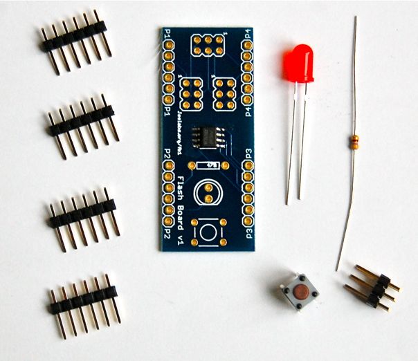
The 24M01 1 Mbit EEPROM is already on the board. The build proceeds essentially in flattest-to-higher order, so that when you turn the pcb around for soldering, you can push down the part properly.
We start with the 470 Ω current limiting resistor for the LED:
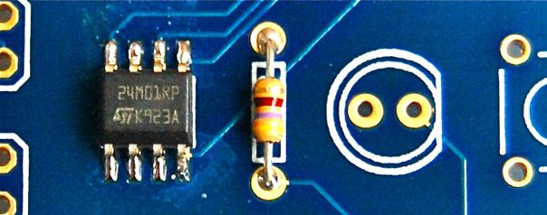
Try to make nice and shiny joints:
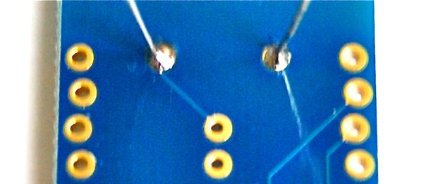
Cut off the excess wires:
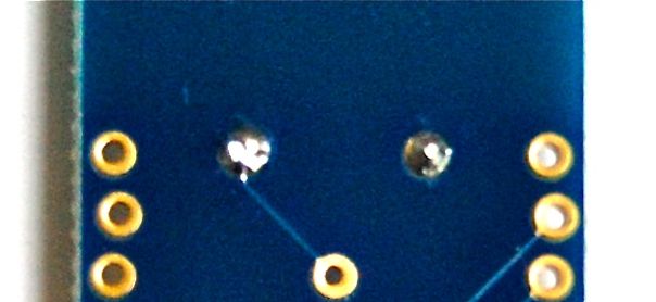
Next is the little start button:
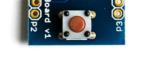
There are four pins to solder:
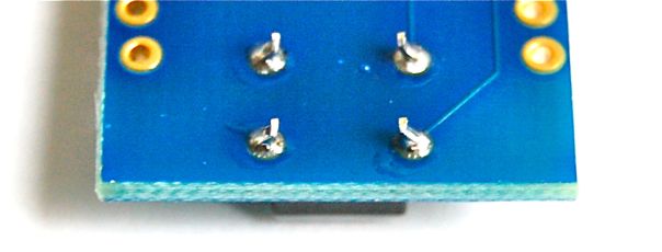
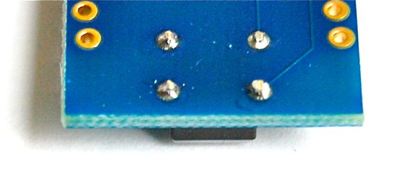
They are a bit long, so it’s best to cut them off:
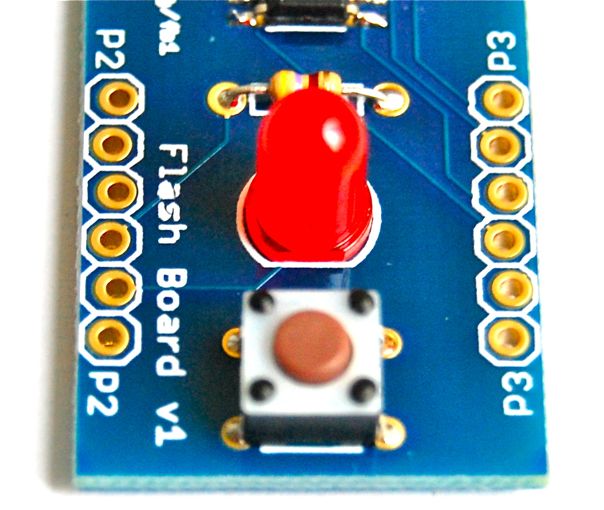
Next, the LED. This one is polarized, be sure to put it in the right way:
The last component on the top is the 2×3-pin ISP header:
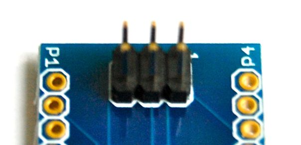
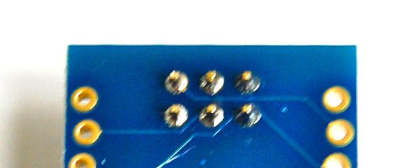
Again, make sure all pins have good solder joints:
Now, all we need to do is solder in the 4 6-pin headers. The easiest way to do so is to push these headers into a JeeNode for proper positioning:
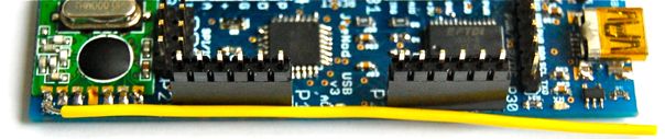
The push the Flash Board on top and you’ve got a convenient way to solder them:
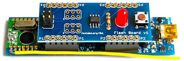
That’s it, done!
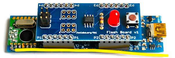
Now you can upload the isp_capture.pde sketch on this page and use this brand new ISP programmer.
Happy programming!