
The v3 boards are finally ready! Here’s a step by step overview on how to assemble a JeeNode v3 kit:
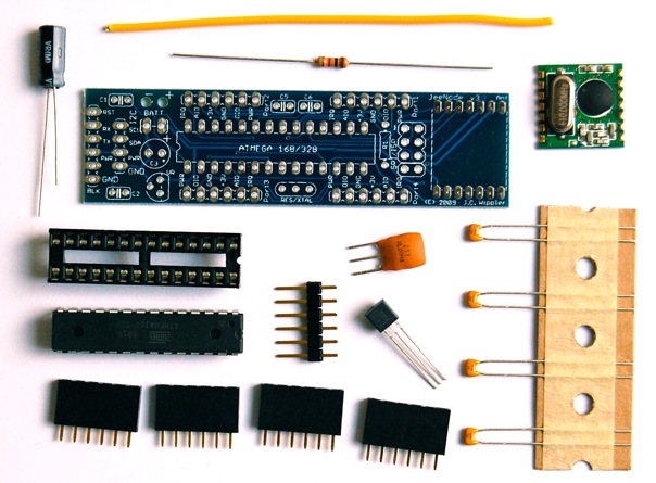
You’ll need some basic skill at soldering but don’t worry, as there are only a few parts to solder on. The best way is to start with the lowest-profile part, that way you can place things flat on the table and press down to keep the parts in place. So let’s start with the 10 KΩ resistor:
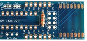
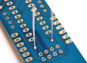
Turn the board around and solder the leads:
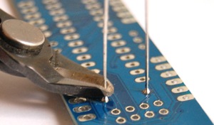
Then carefully cut them off:
Continue in a similar vein with the four 0.1µF ceramic capacitors:
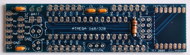
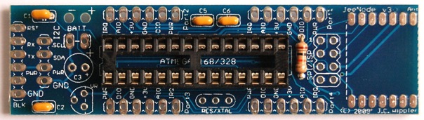
Next the IC socket, which is a bit more work. The best thing is to solder two diagonally opposite pins, then check that the socket is pushed in all the way:
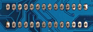
If not, reheat and fix it. Then solder the remaining 26 pins:
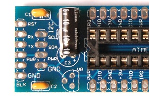
The 10 µF electrolytic capacitor is polarized – there is a “+” marking to indicate which way it should be soldered in. I normally bend the leads first and then make it lie flat on the board:
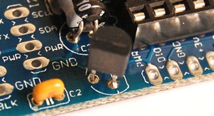
Next the voltage regulator IC. This one needs special attention because it has to be mounted differently from what the marking on the board says. The reason is that the board was designed for an LP2950, but the kit includes an MCP1702 which has a different pinout. Here is how it should be mounted:
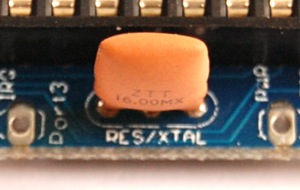
The 16 MHz resonator is next, it’s the tallest part on the board:
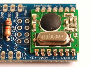
You’re almost there now. The radio module is a surface mounted module, which needs a slightly different approach. Put a bit of solder on one pad, then place the module over it and reheat to stick it in place:
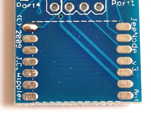
Once correctly positioned, add solder to each of the remaining pads to make shiny round joints:
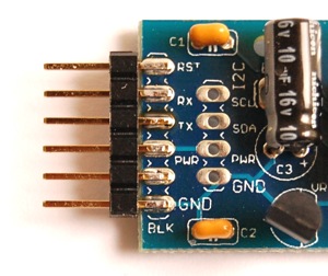
The 6-pin male FTDI connector can now be soldered on, I usually mount it sideways, but the choice is yours:
A simple wire acts as antenna for the radio – attach it to pin 1 of the radio module. You can bend it as needed afterwards. I used a red wire, even though the kit probably has a yellow one.
One more step and you’re done: add the four 6-pin port headers.
Good, the soldering is over. Now bend the pins of the ATmega microcontroller slightly inwards so it fits into the socket. Make sure you only press it firmly down after all the pins are in the proper position.
Voilá! Your finished JeeNode:
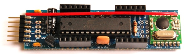
If you have a USB-BUB adapter, you can now plug it in and try out the board (note the 3.3V jumper – the JeeNode uses 3.3V logic signals). The ATmega that comes with the kit is pre-loaded with the RFM12demo sketch to get you up and running in no time:

That’s it. Congratulations with your new JeeNode v3!