Another post about the JET project. This time
around, I’m trying to come up with simple data structures to get the job done,
i.e. supporting a PureData-like dataflow engine, able
to fit in very small µC setups.
That means minimal redundancy, given the limited amount of RAM. One useful
trick is to store int indices where possible, instead of 4-byte pointers to the
various items.
Apart from processing dataflow messages, I also want the whole setup to persist
across power cycles, i.e. the entire dataflow circuit has to be stored in
flash or in EEPROM.
Here is a first tentative design. It may not make much sense to you right now,
but I need these diagrams - as “notes-to-self” - even if some will change again
later on.
The gadget is the central object. Each one has “inlets” which accept
messages and “outlets” that can send out new ones:
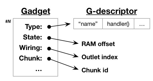
These gadget objects (i.e. instances) have a fixed size, their array index is
used as “id”.
The “type” field refers to the actual code for the gadget, which will be called
as follows:
myHandler(int id, int inlet, Value msg);
The “state” points to a RAM area allocated for that gadget, “wiring” determines
where to send each outgoing message, and “chunk id” refers to optional GC’d
memory.
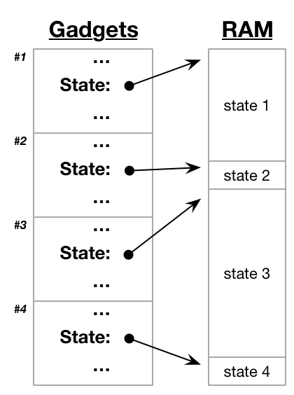
To save space, “state” is an array offset. The size of each area can be
calculated from the next gadget’s state offset, since all areas are allocated
in the same order as the gadgets:
The same trick is used for all the “wiring” entries, since each gadget can also
have its own specific number of outlets:
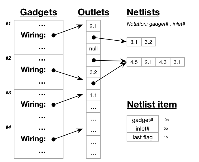
In the example shown above, gadget #1 has 5 outlets, #2 has 1, and #3 has 3.
Note that there will need to be a dummy last gadget to take care of the boundary
conditions.
Each outlet points to a “netlist”, this is an ordered list of inlets to receive
that outlet’s messages. If an outlet has nothing attached to it, its netlist
will be null (see gadget 1, 3rd outlet). Multiple outlets can send messages to
the same net (i.e. unlike direct electrical wiring, but like
open-collector/diode logic).
When a netlist has only a single entry, that entry is stored in the outlets
array itself.
All the above data structures, except states and chunks, can be ROM-based. Since
they are just data, the idea is to store them in flash memory, ready for the JET
engine to pick up and “execute” on power-up.
For now, I’m assuming there will be very little memory. Gadgets take up 8 bytes,
each outlet is 2 bytes, and netlists also need 2 bytes per entry. The limits
I’ve chosen allow at most 1000 gadgets, 250 gadget types, 4000 outlets, and
16000 netlist entries. These limits are sufficient for most of the low end
STM32’s I’d like to run this on. A mere 100 gadgets should already be enough for
a range of non-trivial circuits, I expect.
The way it’s meant to be used, is that there will be a fixed firmware image
with the JET engine core and all supported gadget types (i.e. handlers)
built-in, and that the “circuit” (i.e. application) is written into a separate
area in flash or EEPROM.
Seen from another angle: the JET engine will take care of event handling and the
call graph (defined as data, not code!), while the gadget handlers act as the
components from which the application is constructed. All the information flow
between gadgets takes place as (GC’d) messages, but the gadgets themselves can
process and save their own state in whatever (efficient) way they like.
Note that this is just a very early design / thought experiment. There’s no
code yet to verify that it’s feasible and makes sense…
For comments, visit the
forum.