
This is going to be one of those long posts again, with lots of pictures…
I’ve switched to a new Bridge Board v2 revision, which differs only in some minor ways from the BB v1, so this also applies to that board. The changes are:
- the FTDI connector orientation has changed to match the underlying JeeNode
- one extra breadboard pin on the right, to better match the large breadboard
- minor tweaks to layout and labeling
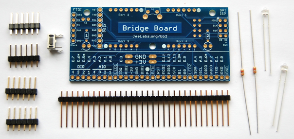
Since this is an assembly guide, let’s start with the parts included in the kit:
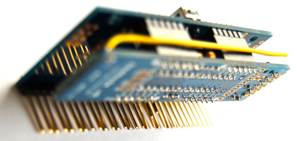
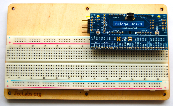
And here’s what we want to end up with – a module which plugs into a breadboard:
Ok, let’s get started… there are two current limiting resistors for the on-board LEDs. I prefer to mount them on the bottom of the board, because that leaves the “1” and “2” labels clearly visible on top:

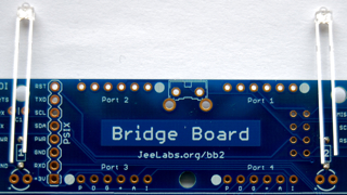
Everything else is soldered on the top side of the board. Let’s start with the LEDs. These are polarized, so make sure to insert them properly:
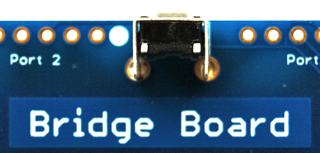
The only other component left is the push-button:
Congratulations! All that remains is to solder on the various pin headers.
There are two types of pin headers on this board: 4 sets of 6 pins to connect a JeeNode, and a long row of (long) pins to stick this bord into a breadboard.
Let’s start with the shorter JeeNode headers first. The easiest way to solder them, is to push these 4 headers into a JeeNode, to hold them in place:
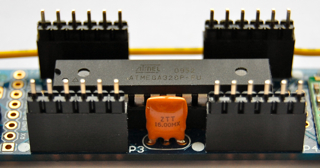
Then, place the board on top, wiggle a bit until all the pins stick out, and solder those 4×6 pins in place. The result shouls look something like this:
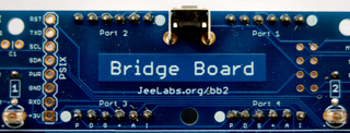
For one of my Bridge Boards, I wanted the ability to easily add one or two plugs, so I decided to replace two of the included headers by 6-pin “stacking headers” (they were recently added to the shop). The result looks like this:
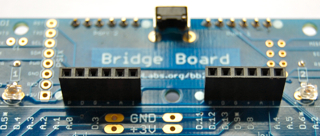
Ok, last step: soldering in the long pins for attaching the breadboard. This is slightly trickier than I had anticipated, because the staggerd holes make insertion of a long strip of pins very hard. But first, make sure you break or cut off a little 2-pin header. This will be used later, as GND/+3V for the supply rails on the breadboard:
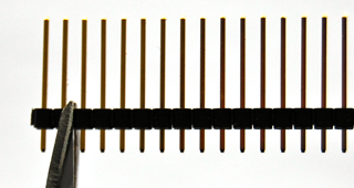
The next task is to get those 30 long pins into the board. I tried a bit, and then decided to cut my strip into a couple of smaller pieces instead:
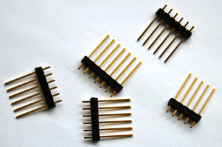
Why struggle, when it doesn’t really matter after all anyway, right? Those smaller pieces are easier to push into the board. The result should look like this:
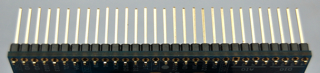
Now you can solder those pins in. All 30 of ’em, please (or 29 for version 1).
The very last step is to solder the 2 pins for the supply rails. There are two different holes for this. If you use the large breadboard from Jee Labs, use the right-most pair, when looking from the labeled top side of the board. The other holes are offset, because some breadboards don’t have the supply rails aligned to the rest of the holes.
Once you’ve verified the proper choice for these pins, you can solder them in.
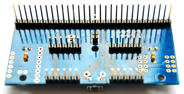
That’s it! You’re done! Here is what it looks like from the bottom:
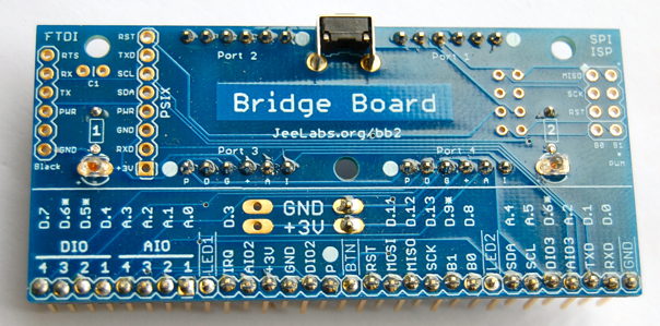
Here’s what it should look like from the top side:
And if you’re using the JeeNode Experimenter’s Pack, then this is what the final setup will look like:
There are some very important details and caveats when using all the pins and headers on the Bridge Board, because some of them will require additional headers and connections with the JeeNode itself.
But that’s worth a separate post, so I’ll go into that tomorrow…